- Research
- Open access
- Published:
Study on track planning problem of multi-constrained and double-targeted
Journal of Mathematics in Industry volume 10, Article number: 21 (2020)
Abstract
Aiming at the positioning error of the aircraft, the error accumulation to a certain extent may lead to the failure of the mission. A track correction method based on oriented graph search was proposed, and the dynamic programming idea was applied to solve the path optimization problem. Firstly, the correction points in the flight space were preprocessed, and the planning of the correction points in the flight space was transformed into a graph theory problem. It effectively solves the problem that traditional methods did not adapt well to dynamic changes in flight space. And the problem of too high complexity in the calculation space. Using the dynamic programming idea to carry out the flight path planning for the flight space, the path-correction number optimal double-objective model is comprehensively established. Finally, the oriented graph and dynamic programming ideas were used to solve the problem, and the visual analysis of the aircraft track was realized. The simulation results show that the established path-corrected optimal double-objective model can calculate an optimal track with relatively small correction times and short length.
1 Introduction
The rapid planning of tracks in complex environments is an important issue in the control of intelligent aircraft. Due to system structure limitations, the positioning system of such aircraft can’t accurately locate itself. Once the positioning error is accumulated to a certain extent, the flight task may fail. Therefore, correcting the positioning error during flight becomes a hot issue in the rapid planning of the track.
Track planning referred to the optimal flight path of an aircraft that meets certain performance requirements and a series of constraints under the premise of a specific mission objective [1]. It was essentially a multi-constrained multi-objective optimization problem. Aircraft track planning played an important role in mission planning, and was the core of the aircraft mission security technology [2]. It was generally divided into two levels: overall reference path planning and local track dynamic optimization [3]. The aircraft optimizes the local track dynamics based on real-time information (such as obstacles, terrain, etc.) around the overall reference track to generate an optimal track.
At present, the multi-constrained multi-objective path planning research uses objective function weighting to establish mathematical models. Dijkstra algorithms [4], genetic algorithms [5], particle swarm optimization [6] etc. are used to obtain optimal tracks. It was essentially an algorithm based on mathematical models. Due to the complexity of the actual flight environment, Shen and Cheng [7] based on the principles of geometry of space structure divided according to specific rules, reduced the complexity of the problem. Song and Dai [8] proposed an improved fast-spreading random number, combining incomplete constraints with bi-directional multi-step extended RRT search algorithm. Improving search efficiency and ensuring the feasibility of the path, but the algorithm only considers the static environment. Under the track planning problem, the practicality is not strong. Hen and Dai [9] introduced gene contrast in genetic algorithm to improve the genetic probability of optimized genes and enhance the real-time performance of track planning. However, the algorithm needed to update environmental information in real time, which makes the calculation amount larger. These algorithms have achieved certain effects in practical applications, but they do not have good universality. And can’t effectively track the flight space for dynamically changing flight space.
Based on the above problems, this paper combines static track and real-time performance, and proposed a track correction method based on oriented graph search. It used oriented graph and dynamic programming idea to solve the problem, and realized the visual analysis of aircraft track.
2 Establishment and solution of multi-constrained and double-targeted
2.1 Problem description
Correcting the positioning error during flight is an important task in the intelligent aircraft track planning. It is required to design a track planning algorithm that makes the entire track length as small as possible during the flight and the optimal path with the least number of corrections in the corrected area. To make the following assumptions for analysis.
The aircraft needs to correct the positioning error during flight. There are some safe positions in the flight area (called correction points) that can be used for error correction. When the aircraft reaches the correction points, it can correct the error according to the error correction type of the position. The position of correcting vertical and horizontal errors can be determined before track planning according to the terrain.
-
(1)
Assume that the vertical and horizontal errors of the initial point are both 0. For every 1 m flight, the vertical error and horizontal error will be increased by σ dedicated unit, hereinafter referred to as the unit.
-
(2)
It is assumed that the vertical error of the aircraft is not more than \(\alpha _{1}\) unit, and the vertical error correction is performed when the horizontal error is not more than \(\alpha _{2}\) unit. The vertical error of the aircraft is not more than \(\beta _{1}\) unit, and the horizontal error is corrected when the horizontal error is not more than \(\beta _{2}\) unit.
-
(3)
If the vertical error and the horizontal error can be corrected in time, and the vertical error and the horizontal error are less than θ units when the end point is reached. The aircraft can fly according to the predetermined route, and the error correction is performed through several correction points to finally reach the destination.
-
(4)
After the vertical error correction of the aircraft at the vertical error correction point, the vertical error will become 0, and the horizontal error will remain unchanged. After the horizontal error correction of the aircraft at the horizontal error correction point, the horizontal error will become 0. Meanwhile, the vertical error will remain unchanged.
2.2 Establishment of oriented graphs
All the possible flight path nodes in the flight process are arranged in chronological order, and the track path problem can be solved by the establishment of the oriented graph [10]. The track between correction points is the oriented edge of the directed track map. Due to the assumption that the condition exists, the range of the directed track path from the starting point to the end point is reduced, which greatly reduces the complexity of the search algorithm. The specific steps for establishing the directed track map are as follows.
-
(1)
Determine the main direction from the starting point A to the destination B.
-
(2)
The arbitrary correction points (including the starting point) are used to establish the dividing plane with the main direction as the normal vector.
-
(3)
Search all points on the side of the main plane of the split plane (without the end point).
-
(4)
If the current horizontal and vertical errors are both 0, all reachable correction points are found according to the constraints.
-
(5)
Add a path whose current point points to the reachable point.
-
(6)
Perform the above operation on all points in the space (without the end point).
Schematic diagram of the establishment of the directional track maps are shown in Fig. 1.

Schematic diagram of oriented graph
2.3 Multi-constraint track planning model
The flight path planning process is based on the track length and the number of corrections of the corrected area. There are a total of \(m + 2\) track nodes, including the starting point and destination, which are represented by \(P = \{ A,N_{1},N_{2}, \ldots ,N_{m},B\}\).
-
(1)
Total track length:
$$ f_{L}(P) = \sum_{i = 1}^{m} \operatorname{dis}(N_{i},N_{i + 1}) + \operatorname{dis}(A,N_{1}) + \operatorname{dis}(N_{m},B). $$(1)Among them dis indicates the Euclidean distance between two points in space.
-
(2)
Number of times the area has been corrected:
$$ f_{C}(P) = \sum_{i = 1}^{M} u_{i}(x). $$(2)Among them \(u_{i}(x)\) indicates the number of corrections at the i-th track node.
$$ u_{i}(x) = \textstyle\begin{cases} 0,&\text{others}, \\ 1,&\delta h_{i}(x) < \varphi \text{ or }\delta v_{i}(x) < \varphi. \end{cases} $$(3)Among them φ represents the minimum value of the horizontal error sum or the minimum vertical error sum before the i-th track node, \(h_{i}(x)\), \(v_{i}(x)\) indicates the horizontal and vertical errors of the i-th track node.
In summary, the aircraft dual-target trajectory planning problem can be described as the following path-correction number optimal model.
\(L_{\min } \) indicates the shortest sailing length, \(L_{i}\) sailing distance representing two adjacent correction points.
2.4 Model solving algorithm based on oriented graph
Usually, the sub-strategy of the optimal strategy of an overall process must be the optimal strategy. Dynamic programming transforms the process that requires multi-stage solving into a series of single-stage solving problems. Recursive use of mutual relations between the various stages, gradually solving process to get the optimal solution of the last problem [11]. In this paper, the idea of dynamic programming is used to solve the optimal track segment in discrete flight space until the target point gets an optimal track. The algorithm of the aircraft path planning algorithm are as follows.
- Step 1::
-
Constructing an oriented graph.
- Step 2::
-
Initialize the current position and the error before correction.
- Step 3::
-
According to the constraints, it can be judged whether it can reach the end point directly, if it can, then turn to step 7, if not, then proceed to the next step.
- Step 4::
-
Determine whether there is a feasible path in the current location. If it exists, proceed to the next step. If it does not exist, execute step 8.
- Step 5::
-
Select a path, calculate the length of the path and correct the cumulative error. According to the correction type of the point to determine whether the correction can be made, if possible, proceed to the next step, if not, delete the path and return to step 4.
- Step 6::
-
Update the current position and correct the accumulated error according to the correction type at that point, return to step 3.
- Step 7::
-
Determine whether the current path is better than the existing path. If not, delete the path and return to step 2. Otherwise, replace the existing path with the current path.
- Step 8::
-
Determine whether the current point is the end point, if yes, output the optimal path and correction error information. Otherwise, update the current position to the previous position and turn to step 4.
The algorithm flow block diagram is shown in Fig. 2.

Track planning model solving process
We explained it on a two-dimensional plane according to the specific steps in the flow chart.
-
(1)
Construct the initial oriented graph as shown in Fig. 3.
Figure 3 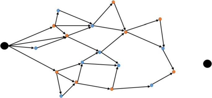
Initial oriented graph
-
(2)
Search for a feasible track, record the track and delete the path of the last correction point in the oriented graph as shown in Fig. 4.
Figure 4 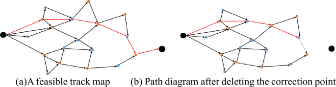
Track Search Schematic 1
-
(3)
Search for another better track, replace the existing track and update the oriented graph as shown in Fig. 5.
Figure 5 
Track Search Schematic 2
-
(4)
Two horizontal corrections in the search process, causing the vertical error to be too large to continue moving forward. Therefore, delete the corresponding path as shown in Fig. 6.
Figure 6 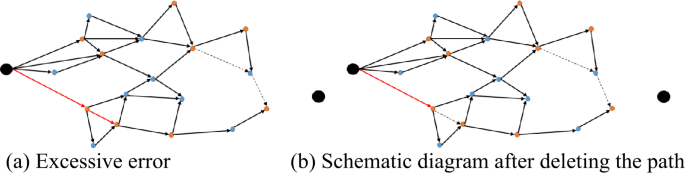
Track Search Schematic 3
-
(5)
There is no feasible path at a certain correction point, so the corresponding path is deleted as shown in Fig. 7.
Figure 7 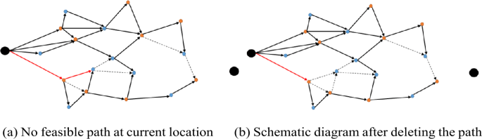
Track Search Schematic 4
-
(6)
The end point is reached at the front position, and there is no feasible path, the algorithm is terminated, and the final result is output as shown in Fig. 8.
Figure 8 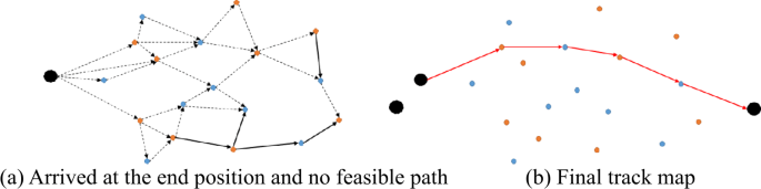
Track Search Schematic 5


3 Example simulation results and analysis
The path-correction number optimal model is used to solve the data in the “16th Graduate Mathematical Modeling Contest”. The environment used for the experiment was Intel(R) Core(TM) i7-7700HQ @ 2.80 GHz; x64-based processor, MATLAB V2018a.
Directed track maps are constructed based on the position information of the correction points in the data set 1, 2. We use the dynamic programming algorithm to obtain the adjacent optimal segments reachable by the adjacent correction points. And obtain the optimal track path length from the start point to the end point. The number of correction points passing through from the starting point to the destination point are the least. According to the model solving algorithm, the following experimental results are obtained.
The space track plan in Data Set 1 was shown in Fig. 9, which shows all the correction points and destinations that the aircraft passes except the departure point. The specific experimental resulted consist of vertical correction error accumulation and horizontal correction error accumulation. The correction points in the figure were marked in yellow, and the start and end points were marked in red. And the track direction was from left to right. For example, the vertical correction error of the end point was 28.5 units, and the horizontal correction error was 16.3 units. By calculation, the optimal track length in data set 1 was 108.99 km, and the number of corrections that need to be passed was 8 times.

Data set 1 track planning path
The space track plan in Data Set 2 was shown in Fig. 10, which shows all the correction points and destinations that the aircraft passes except the departure point. The specific experimental resulted consist of vertical correction error accumulation and horizontal correction error accumulation. By calculation, the optimal track length in data set 2 was 110.00 km, and the number of corrections that need to be passed was 12 times.

Data set 2 track planning path
The error correction point number and the track planning result of the error before the aircraft from the starting point are shown in Table 1, Table 2. It can be seen from Table 3 that the number of corrections will affect the path length of the aircraft to a certain extent, and it will also affect the complexity of the algorithm.
The k-dimensional tree (abbreviated as KD-tree) performs the nearest point search to improve the search speed. Since the oriented graphs are different according to the scatter position, the time complexity can’t be directly calculated. Therefore, a large number of experiments are taken to obtain an average value to obtain a relationship between the data size n and the calculation operation time. According to the scatter distribution density of the data given by the problem, 50 sets of test models are randomly generated for each value of n to conduct experiments. The experimental results are shown in Fig. 11. It can be observed that the average running time increases with the increase of the data size n.

Quantity-time-consuming graph
4 Conclusion
In this paper, the real-time requirements of the aircraft in space flight, the dynamic changes of the flight environment with time, and the accuracy requirements of the positioning error in the safety area were considered. The plan of correction points in flight space was converted into a graph theory problem to solve. A dual-target model with optimal path-correction times was established. The problem that the positioning system cannot accurately position itself due to the structural limitation of the aircraft system was solved. The model was tested using two types of data sets, and the flight path optimization diagrams under the two data sets were drawn to obtain the best track path length and minimum number of aircraft corrections.
Experiments show that the model established by the algorithm can’t only obtain the optimal path, but also the minimum correction points. The optimal path length obtained in data set 1 was 108.99 km, the number of corrections was 8 times. The optimal path length obtained in data set 2 was 110.00 km and the number of corrections was 12 times, and the space complexity and time complexity of the algorithm show good performance. This also lays a solid foundation for the follow-up study in this paper to conduct track planning in a complex and dynamic environment.
Abbreviations
- KD-tree:
-
k-dimensional tree. It is a data structure that divides data points in k-dimensional space
References
Ming L, Tao L, Xiaohong S. A survey on key issues of cooperative task planning for 3D multi-UAVs system. Intell Comput Appl. 2016;1(6):31–5.
Zun Y, Huming L. Simulation of cooperative reconnaissance path planning algorithm for multiple UAVs. J Syst Simul. 2007;19(2):433–6.
Pin D, Chun Y. Introduction of air vehicle path planning algorithms. Flight Dyn. 2005;23(2):10–4.
Yaohong Q, Yintao Z, Youmin Z. A global path planning algorithm for fixed-wing UAVs. J Intell Robot Syst. 2018;91(3/4):691–707.
Silva Arantes JD, Silva Arantes MD, Motta Toledo CF, Júnior OT, Williams BC. Heuristic and genetic algorithm approaches for UAV path planning under critical situation. Int J Artif Intell Tools. 2017;26(1):30–6.
Wu X, Bai W, Xie Y, Sun X, Deng C, Cui H. A hybrid algorithm of particle swarm optimization, Metropolis criterion and rts smoother for path planning of uavs. Appl Soft Comput. 2018;73:735–47.
Lincheng S, Jing C, Lan W. Overview of air vehicle mission planning techniques. Acta Aeronaut Astronaut Sin. 2014;35(3):593–606.
Jinze S, Bin D, Enzhong S. An improved RRT path planning algorithm. Acta Electron Sin. 2010;38(2A):225–8.
Pinchuan H, Shuling D. Improved 3-D real-time trajectory planning algorithm for UAV. J Beijing Univ Aeronaut Astronaut. 2010;10:1248–51.
Jing Y. Application of graph theory in track management. Radioengineering. 2004;34(1):27–30.
Yingding F, Xiaoyu C, Yinghui T. Optimization theory and method. 2008.
Acknowledgements
At the point of finishing this paper, I’d like to take this opportunity to show my sincere gratitude to my supervisor, Mr Ding and Mr Xie, who has given me so much useful advices on my writing, and has tried his best to improve my paper. Secondly, I d like to express my gratitude to my classmates who offered me references and information on time.
Availability of data and materials
The data used to support the findings of this study are available at the question F of the 2019 postgraduate mathematical contest in modeling website (https://cpipc.chinadegrees.cn/cw/hp/4). Additional files 1 and 2 contain raw data for data set 1 and data set 2.
Funding
There is no funding for this research.
Author information
Authors and Affiliations
Contributions
NY mainly carried out algorithm research and writing manuscripts. DXF and XXJ are mainly responsible for supervising and revising papers. ZQY is mainly responsible for algorithm research and software. ZJY is mainly responsible for software programming. All authors read and approved the final manuscript.
Corresponding author
Ethics declarations
Competing interests
The authors declare that they have no competing interests.
Electronic Supplementary Material
Below are the links to the electronic supplementary material.
Rights and permissions
Open Access This article is licensed under a Creative Commons Attribution 4.0 International License, which permits use, sharing, adaptation, distribution and reproduction in any medium or format, as long as you give appropriate credit to the original author(s) and the source, provide a link to the Creative Commons licence, and indicate if changes were made. The images or other third party material in this article are included in the article’s Creative Commons licence, unless indicated otherwise in a credit line to the material. If material is not included in the article’s Creative Commons licence and your intended use is not permitted by statutory regulation or exceeds the permitted use, you will need to obtain permission directly from the copyright holder. To view a copy of this licence, visit http://creativecommons.org/licenses/by/4.0/.
About this article

Cite this article
Nie, Y., Xie, X., Ding, X. et al. Study on track planning problem of multi-constrained and double-targeted. J.Math.Industry 10, 21 (2020). https://doi.org/10.1186/s13362-020-00089-x
Received:
Accepted:
Published:
DOI: https://doi.org/10.1186/s13362-020-00089-x